Analog Sound Level Indicator Circuit
Overview
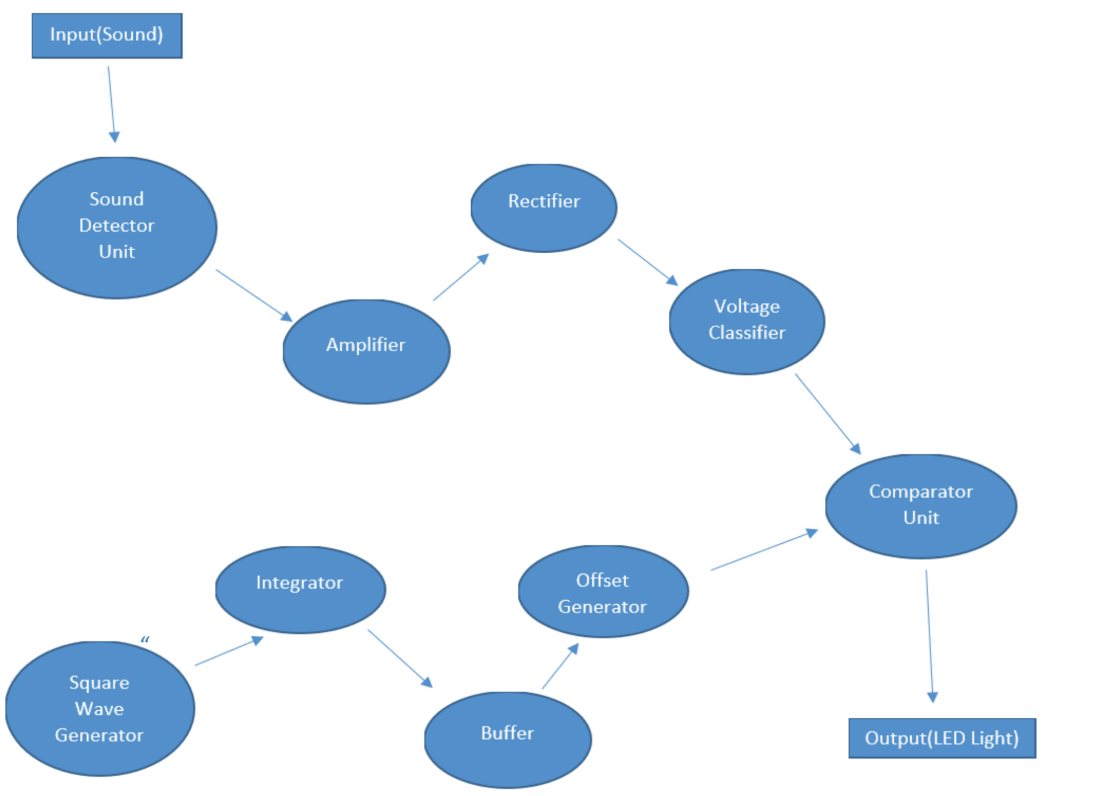
Developed an analog sound level indicator circuit that senses ambient sound amplitude and produces a proportional PWM-driven LED output. The design was fully simulated in LTspice and validated on a breadboard, demonstrating four discrete duty-cycle levels corresponding to increasing sound intensities.
Components & Technologies
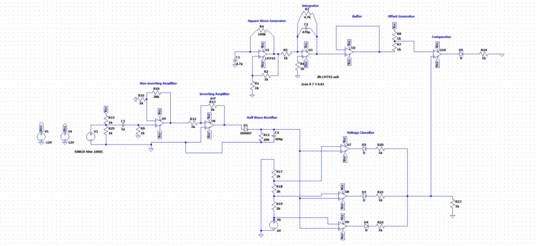
- Sensor & Pre-amp: Electret condenser microphone with a custom driver (6 V bias and coupling capacitor)
- Amplification: Two‐stage op-amp chain using LM741 (non-inverting + inverting) for ~20–60 mV → multi-volt swing
- Signal Conditioning: Half-wave rectifier with smoothing capacitor and potentiometer-tuned diode network
- Classification: 3-level voltage classifier (LM741 comparators + diode-OR) mapping 0–2 V, 2–4 V, 4–6 V, >6 V to discrete DC levels
- PWM Generation:
- Square Wave Oscillator (≈1 Hz) → Integrator → Triangular Wave
- Offset Generator to shift the triangle baseline
- Comparator to compare DC level vs. triangle → PWM
- Output: LED driven by PWM; duty cycles of 0%, 25%, 55%, 90% for 10 mV, 30 mV, 40 mV, 50 mV inputs
Key Results
Duty Cycle Mapping:
Input (mV) Simulated Duty Cycle 10 0% 30 25% 40 55% 50 90% Validation: Hardware measurements closely matched simulation, with minor deviations due to component tolerances.
Project Workflow
- Design & Simulation (LTspice)
- Equipment Selection & Cost Analysis (~$20 total)
- Breadboard Implementation & Power Analysis
- Functional Testing (DSO & multimeter)
- Comparison of Simulation vs. Physical Results