Real-Time Sound-Responsive Motor and RGB LED Controller
Introduction
In this project, I built a real-time audio-driven control system that samples sound via a microphone, computes its dominant frequency and amplitude, and then adjusts a DC motor’s speed and an RGB LED’s brightness and color accordingly. 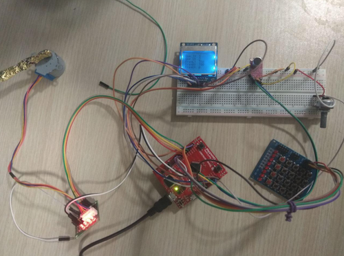
Code Overview
The firmware is organized into modular components:
- ADC Sampling: Capture 256 audio samples from the microphone.
- FFT Processing: Configure the DSP library to perform an FFT on the samples and extract the dominant frequency and amplitude.
- Motor Control: Drive a DC motor at a speed proportional to the detected frequency.
- Direction Switching: Change motor rotation direction via a GPIO Port F interrupt.
- LED PWM: Generate PWM signals to modulate RGB LED brightness based on amplitude.
- Threshold Configuration: Use a potentiometer (and later a keypad) to adjust amplitude and frequency thresholds.
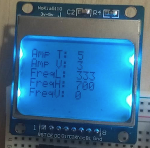
- LCD Display: Present current readings and threshold values on an LCD.
Initialization
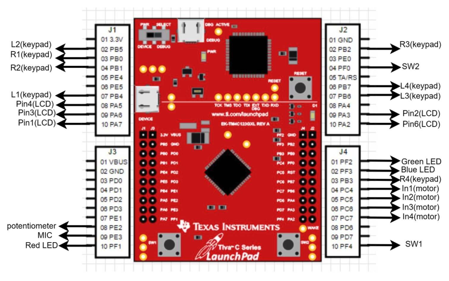
At startup, all peripherals are configured: GPIO ports, timers (GPTM 0 & 1), ADC modules, UART, and SysTick. Memory buffers are pre-allocated for interrupt handlers, and static strings are stored in flash to minimize runtime writes.
Main Loop
The main loop:
- Every ~1 second, calls a subroutine to refresh amplitude, frequency, and threshold variables.
- Polls the keypad—pressing K13 enters “threshold-set” mode; K14, K15, and K16 select amplitude, low-frequency, or high-frequency thresholds, respectively.
SysTick Handler
A SysTick ISR samples the microphone (ADC sequencer 2) and potentiometer (sequencer 3), storing samples until 256 are collected. It then invokes the FFT routine to determine the dominant frequency and amplitude and computes a corresponding motor speed.
GPIO Port F Interrupt
Pressing SW1 or SW2 triggers a Port F interrupt. The ISR (SwitchHandler) toggles the motor’s rotation direction, clears the interrupt flag, and returns promptly to avoid interrupt contention.
Motor Rotation
GPTM Timer0 generates a periodic interrupt that drives the motor. In its ISR, the code:
- Checks the current rotation direction.
- Updates the
TAILRregister: smaller values for higher detected frequencies (faster motor speed), larger values for lower frequencies (slower speed). - Maintains a high interrupt priority so motor pulses aren’t disrupted.
PWM for LEDs
GPTM Timer1 generates PWM signals for the RGB LED based on amplitude. The amplitude is mapped to a 0–100 range and loaded into TAILR for the on-time; 100 – amplitude sets the off-time. Threshold checks are also performed here.
LCD Display
The LCD continuously shows the set thresholds and current amplitude/frequency readings. To prevent flicker, updates occur at a reduced rate governed by the main-loop counter.